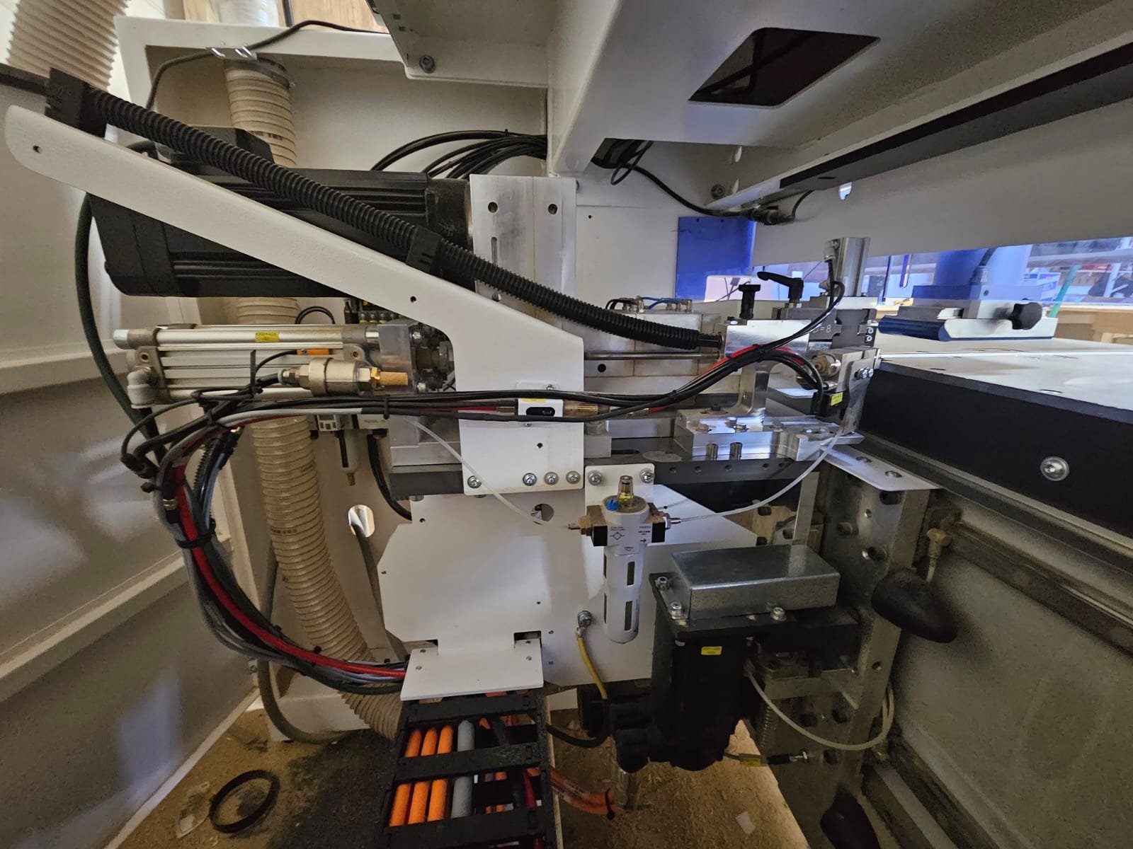
Homag BMG311 5-Axis CNC 2013 (Used)
BMG Venture 316 features one (1) 16-spindle (V12 + H4) flexible drilling unit and one (1) heavy-duty 5-axis Drive 5C router spindle unit which can be used for both 3-axis and 5-axis machining, giving this machine the highest level of flexibility for a wide range of complex manufacturing operations.
5-Axis Main Router Spindle – 10/12 kW Current-Controlled "Drive 5C"
· Gimbal (cardanic) type 5-axis router spindle for routing, drilling, and sawing at an arbitrary angle to the panel
· HSK-63F - DIN 69893 spindle taper
· speed regulated (closed-loop current-controlled), three-phase asynchronous 10 kW (13.4 hp) motor - S1 rated, (12.0 kW (16 hp) - S6 rated), with high torque at low spindle speeds, and with full nominal power from 12,000 rpm for exceptional power output.
14 Position HSK-63F Plate-Type Tool Changer D=130 Below
Homag Unit #7455 (1 of)
· for tools and processing units (aggregates) with HSK-63F interface
· plate-type tool changer for up to 14 tool/unit places
· maximum rotating tool weight of 6 kg (13.23 lbs.) including tool holder
· maximum processing unit weight of 10 kg (22 lbs.)
· maximum total weight of all equipment is 70 kg (154 lbs.) distributed evenly
· following tool combinations are possible:
o 14 x maximum diameter of 130 mm (5-1/8") or
o 7 x maximum diameter of 180 mm (7-3/32") and
7 x maximum diameter of 70 mm (2-3/4")
· maximum tool diameter for sanding tools is 200 mm (7-7/8")
· with Drive 5C/+: saw blade of 350 mm diameter and "A" dimension of 50 mm can be interchanged into the tool changer.
Saw Blade D=350 mm with Tool Chuck for Drive 5C/5C+
Homag Unit #7942 (1 of)
· special use HSK-63F tool chuck with "A" dimension = 50 mm for insertion into the Drive 5C/5C+spindle
· tool arbor D=30 mm
· reference circle diameter 90 mm, M5 8 x 45º
· design of the chuck appropriate for clamping the saw blade alternately with washer disk for optimum concentricity or with countersunk head screws for miter cuts.
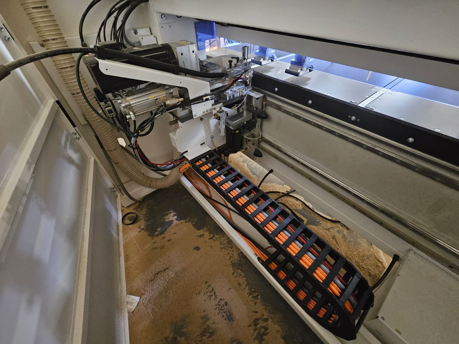
16-Spindle Boring Head: 12 Vert., 4 Horiz., 0º/90º Saw
Homag Unit #7472 (1 of)
twelve (12) spindles with up to a maximum of 35 mm (1-3/8") hole;
· with 4 Horizontal Boring Spindles with Grooving Saw - 0°/90° Indexing
o for horizontal drilling in four (4) directions (X+, X-, Y+, and Y-)
o direction of rotation: three (3) left-hand, one (1) right-hand
o one (1) boring spindle prepared for a grooving saw blade for grooving in X- and Y-directions
LED Position Indication System for 1300-1600 mm Consoles
Machine Technical Specifications
controlled axes
six (6) X, Y, Z1, Z2, C, A
axis strokes
X-axis - 4700 mm (185-1/32")
Y-axis - 2450 mm (96-7/16")
Z1-axis - 440 mm (17-5/16")
Z2-axis - 325 mm (12-25/32")
C-axis - ±361°
A-axis - ±100°
axis rapid traverse rate
X-axis - 35 M/min (1378 in./min.)
Y-axis - 60 M/min (2362 in./min.)
Z-axes - 25 M/min (984 in./min.)
table size
4200 mm x 1340 mm (165-11/32" x 52-3/4")
shank size
25 mm (1") maximum
tooling length
(from spindle nose)
230 mm (9-1/32") – for 20 mm dia. tools
165 mm (6-1/2") – for 80 mm dia. tools
A dim. = 50 mm (1-31/32") – for 350 mm dia. saw blade
cutter diameter
max. 180 mm (7-3/32") for routing tools
max. 350 mm (13-3/4") for saw blade (with A dim. = 50 mm)
tool holder* - HSK-63F
two (2) right-hand
collet* - RDO-35
two (2) 25 mm
main spindle power
10 kW (13.4 hp) – S1 rated
12 kW (16 hp) – S6 rated
spindle speed (variable)
1,500 to 24,000 rpm
spindle speed control
one (1) solid-state frequency inverter with closed-loop current-control
boring unit adapter (size/type)
10 mm (straight)
boring unit drill length
70 mm (2-3/4")
boring unit power
2.2 kW (3 hp)
boring unit speed
7,500 rpm maximum
* Combination of tool holder and collet balanced to G2.5 at 24,000 rpm.
Panel Specifications
maximum workpiece length (single operation) with spindle in the vertical position for all router processing units or with spindle in the horizontal position, with panel aligned with side stop pins
4200 mm (165-11/32")
maximum workpiece length (alternating or pendulum operation) with spindle in the vertical position and tooling dia. of 25 mm (1"), with panel aligned with side stop pins
1645 mm (64-3/4")
2615 mm (102-15/16") max. /
500 mm (19-21/32") min.
with dynamic space occupation
maximum workpiece length (alternating or pendulum operation) with spindle in the vertical position for all router processing units or with spindle in the horizontal position, with panel aligned with side stop pins
1470 mm (57-7/8")
2440 mm (96-1/16") max. /
500 mm (19-21/32") min.
with dynamic space occupation
maximum workpiece width with spindle in the vertical position and tooling dia. of 25 mm (1"), using standard front stop pins
1050 mm (41-5/16")
maximum workpiece width with spindle in the vertical position for all router processing units or with spindle in the horizontal position, using standard front stop pins
950 mm (37-3/8")
maximum workpiece width with spindle in the vertical position and tooling dia. of 25 mm (1"), using rear stop pins, and with 150 mm panel overhang at front of consoles
1550 mm (61")
maximum workpiece width with spindle in the horizontal position, using rear stop pins, and tool (& holder) length of 150 mm maximum
1400 mm (55-3/32")
maximum workpiece width with full coverage of the drilling head, using the rear stop pins
1050 mm (41-5/16")
maximum workpiece thickness to the consoles, including any vacuum pod or optional clamping units or customer-provided-fixtures, with tool (& holder) length of 230 mm max.
250 mm (9-27/32")
maximum workpiece thickness to the standard 100 mm vacuum pods, with tool (& holder) length of 230 mm max.
150 mm (5-29/32")
maximum workpiece thickness with standard vacuum pods, without restriction for units & suction
60 mm (2-11/32")
minimum workpiece size
depends on clamping devices, workpiece surface and contour
working height to lower edge of workpiece
960 mm (37-25/32")


